Posts

Showing posts from 2014

24TPI Bandsaw blade experiments

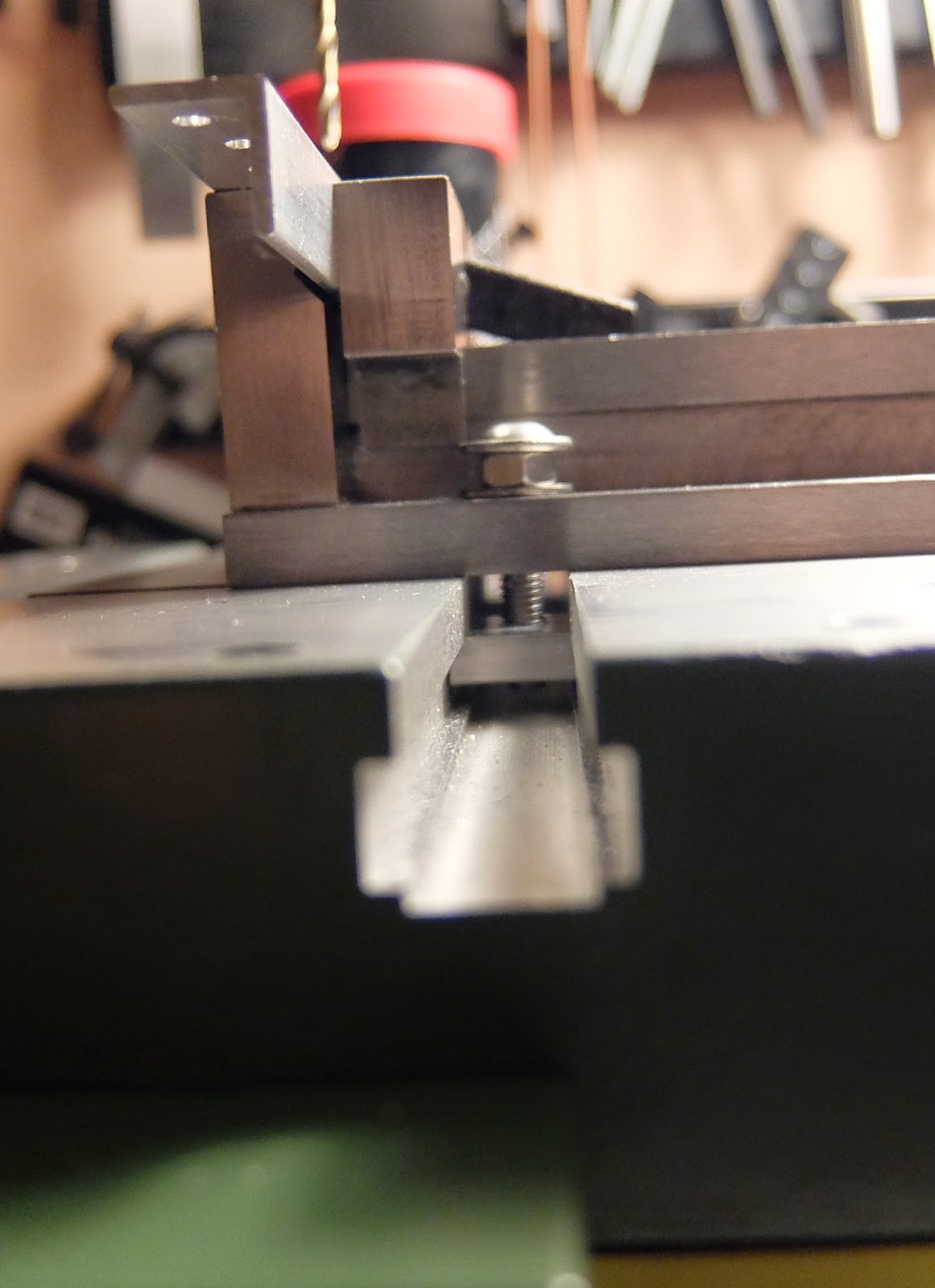
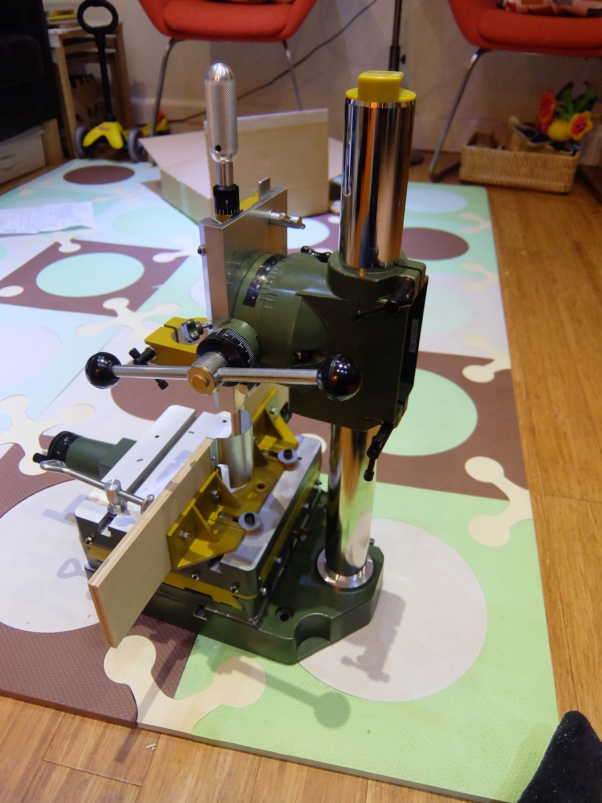
The blade arrived and I've fitted it. I've spotted a neat trick for measuring the tension of the blade, which involves clamping calliper jaws to the blade and measuring the stretch as the blade is tensioned. here for example. I haven't bothered with this yet. I've tried cutting a few different materials. In all cases, it leaves characteristic vertical groves on the work. On solid pine and MDF, this is very fine: A tiny bit of sanding and it's gone. This is also true of aluminium angle. The 8mm aluminium rod is a little more noticeable. 3mm polycarbonate or acrylic is pretty rough. Not really sure what the cause is. Another thing I've discovered about this saw is the t-track for the mitre guide isn't standard, so it's also not possible to buy an after market mitre gauge. That's a shame, because the provided one isn't great. What I'm working on now is a sort of sliding table. I've cut down a strip of hardwood to fit in the mitre

What bandsaw blade?

Turns out that bandsaw blades are made in very long lengths (10m+), then cut to length and welded into a loop. I don't have the equipment to weld them myself, but there are companies like www.justbandsawblades.co.uk  who will weld custom lengths for you. I can choose any blade 6-13mm width. It seems that I need to choose the the number of teeth by the thickness of the material. This is quoted as TPI. There need to be between 2 and 10 teeth in the material at once. I sometimes cut 1/8" angle. This is cut at 45 ° , so that's 3/16'. I guess that's 12-60 TPI. If I cut 20mm stock, I need 2.5-25 TPI. It seems like my actual choices are 14TPI or 24TPI. I don't cut 20mm stock very often, so it makes sense that's the outer limit of the blade. That means 24TPI. I asked the helpful guys at Axminster, and they suggested 24TPI two, which is re-assuring, but I actually bought the blade from justbandsawblades.co.uk. Sadly I haven't got it yet. The blade guide up

Bandsaw

Image
I've been tinkering with my circular saw cross cut guide. It doesn't always produce great results, and it's because the rails aren't all that strong. They aren't that strong because of the saw's low clearance, which make most conventional jigs impractical. Add to this the showers of aluminium chips it produces, and scatters everywhere, and the difficulty of adequately supporting some materials, and I am less than satisfied. It will still work for the other projects I had in mind for it, but for robotics, I've been looking for something else. I'd nearly narrowed it down to two proxxon machines: The FET table saw and the micro band saw (MBS). These both have there down sides: basically the aren't all that powerful, and can only be used with very small work. Then Axminster discounted there hobby bandsaw to £100, and I decided to buy it. This is not without it's issues. In truth, this was a bit of an impulse. What makes the Proxxon micro ba

Work Holding, and tapping is surprisingly easy

Image
I bought this little machine vice from Axminster, before I had the new milling stand and compound table. The reason was the long slots, which would have made it easy to position correctly in the drill press. Unfortunately, the vice slots accommodate a maximum of an M6 bolt. It comes with a bolt with an oversize head, but this is designed for a bigger table: probably a 12mm slot. It turned out not to be hard to fix this however: make an oversized nut with an M5 thread, out of some 5mm thick aluminium flat bar. Here it is: I've never tapped a whole before, and I just have a basic tap and die kit, but actually my first attempts worked fine. Aluminium is of course quite soft, and with a bit of wax on the tap, I got all the way through 5mm in one go. I've carefully fixed the vice square on the table, and don't have to move it - I can just move the table: The vice isn't perfect: it takes a bit of care to make sure the back jaw is what you are using to keep things squ

A quick look at the Proxxon Micromot KT 150 and Proxxon BFB 2000

Image
I brought these home today. Here's a couple of photos: I'm photographing it in the living room, because my shed is filled with boxes, as I'm re-doing the shelving to be more flexible, and lining the walls at the same time. It might be a while before I actually use this! The first picture is the really illustrative one. Just look how solid it is! The movement in all the axis is very smooth. It comes with all the parts greased with something odourless, clear and colourless. I think I'll have to find out what it is. There are a few promising details: The head can rotate, but to zero it, you can lower it down onto the table: the bottom is flat. If you do that, you'll find the zero marker is perfect anyway. I think the fence seems pretty good: certainly it's a quick way to work with wood, and it certainly looks like you could use this as an inverted router table for small work. Perhaps you could even slide something larger along the fence, with the guard se

Proxxon Micromot KT 150 and Proxxon BFB 2000 Arrive

In the end, I chose this combination. It might have been more interesting to have tried the Wabeco, but at this point I'd really like something that works. I was also heavily influenced by all the CNC conversions I've seen for this set up. I hadn't considered using this for PCB milling, but that's definitely a possibility. I found Foxcot  sell these two for £303 delivered. I decided the fact I had never heard of them would be OK since I could pay by Paypal. In the basket they quoted in Pounds, but then passed a price in Euros to Paypal, who's conversion was higher, so I didn't pay. Then I went back to the order status page, and followed the link to complete, which this time submitted the amount in pounds to Paypal. I don't know who made that mistake, but I saved £10. Otherwise I'd have use Conrad Electronic instead. It arrived via UPS, who failed to deliver at the first attempt, because 'No apartment number provided', but the company name was

Scriber Vernier Callipers

Calliper Abuse for Beginners explains how useful callipers are for marking, while the MIT video explains there inaccuracy. These  Scriber Vernier Callipers  seem like a good solution, but are rather pricey. I'd much rather have a digital set, but I guess I could use digital callipers to set them.

Proxxon Micromot KT 150 and Proxxon BFB 2000 vs Wabeco Drilling Milling stand and compound table

I've trying to choose between these two, so I thought I'd make some notes: Proxxon Wabeco Total cost £320.00 £254.00 Column thickness 45 35 Stand Weight 7 13.5 Table weight 4.9 5.7 Width 200 400 Depth 200 180 Height 500 500 Z Travel 65 250 X Travel 150 320 Y Travel 150 100 T-Slot size 10 10 Fine feed yes no The Wabeco stand is heavier, and this is generally a good sign. The set up is also cheaper, and includes a step clamp set. The prices include shipping. The Wabeco stand has an integral Y-Axis, which makes it more flexible. E.g. it could be used with a router, which would tend to be too wide to fit in the Proxxon. The Proxxon components are widely used and reviewed: they are a known quantity. The column thickness, which should be the most important statistic when it comes to accuracy, is significantly greater. It can definitely be converted to CNC.  It's smaller size means it fits better in my work space. It has a Z axis fine feed. Some routers would fi

Drilling again

Image
I discovered these videos , which are an excellent overview if the machine shop, and specifically a machine shop for robotics prototyping. Of course, they have several large expensive machines you simply can't replicate in a home workshop. I've only watched the first one. The second half of that video explains a method for drilling holes very accurately in metal. The basics describe how to mark the work piece, and the accuracy you can expect to get with a few different methods. The accuracy is actually very high - to the extent that the best marking by hand practices can be ignored as a source of errors: drilling is an order of magnitude less accurate even on MITs marvellous drilling machine. Some of the techniques I've already used: using centring drill bits, but I don't have a compound table or centre finder to use the suggested technique. Before I watched that, I bought a machine vice from Warco. It actually seems like a nice piece of equipment: The action is very

Inventor of the copy and paste error.

The long and short are celebrating Larry Tesler , who is, in effect, the inventor of the copy and paste error. If you think I'm being harsh, and this is just the law of unforeseen consequences at work, remember he was a programmer, and probably proceeded to use this 'feature' in his work. I remember using Rational Ada as part of my CS course, back in 1992. I've only recently started using something that resembles a structured editor, with 'refactor' again. In the meantime, it's been cut and paste all the way. I won't, however, be looking back. Goodbye cut and paste, and good riddance. Now there's copy and paste journalism. But that certainly is an unforeseen consequence.

Toggle clamps and safety features

Image
I've recently discovered toggle clamps. You can buy small ones for a fiver, either on ebay, or a spectacular array of clamps are available from Good Hand UK Limited . I haven't bought anything from the latter, I should add though. I bought 4 very cheap ones on ebay, intending to do something better than my previous hold down clamps. I started by attacking one to some aluminium channel. The idea being that it would work like a hold down clamp: hold the back up, the middle down, and press down at the end. I thought the screw holes were M5, found they were M4, and then used M3 screws with a washer. The result was a bit of a bodge. Also, I should have spaced everything out a bit more, but there isn't really room for the result on the drill press. So I re-purposed it to clamp work in place on the circular saw Jig: It's quite primitive: You have to replace the screw with a longer one to clamp thicker work, but for repetitive cuts it's very convenient.

A rethink of the drill table fence

Image
I'd made this very small wooden table with t-slots for my drill press. It's designed along the lines of various other's I've seen. The first version of the fence is a simple bit of aluminium angle. Here it is (after I've removed it):  But it turns out that with some hold down clamps, you can use whatever you have to hand as a fence, and use scraps of timber as sacrifices. I just saw someone doing this in a youtube video, and realised that's what I needed. I've found one place to buy these cheaply: the UJK technology ones at Axminster. I never quite get around to ordering from them because of the delivery charge, these are out of stock anyway, and also, there's no drawing or dimensions. I have a jig making kit (also from Axminster), so I just made these today, using the t-bolts and knobs from the set: The design may not be that well thought out, but they work: it's not a difficult thing to implement. The only problem is that the t-bolts ar

A few enhancements to the cross cut jig

Image
I've upgraded the fence: it extends both sides of the cut, adds support for small work pieces, and now includes a simple depth stop:  Then I cut this new little pile of bits of angle for linear bearings: The old ones varied quite a lot in length, and some didn't prove to be usable. These are very consistent, although occasionally the saw cuts these a little roughly: you have to go slowly to get a good result. The other problem with the jig is that you get aluminium chips on the rails. Maybe I could place a piece of clear plastic between the rails with a slit in it for the blade. It could sit on top of the fence, and does need to go any further back than the beginning of the cut, which won't be far for aluminium. I don't think wood chips will be a big problem. The reason the aluminium chips are such a problem is the saw foot has a little slope at the front, so it climbs onto the chips, trapping them, and then scratching the track. I guess something placed in fr

Cross cut jig

Image
There are plenty of designs for a cross cut jig out there. I have a couple of extra requirements: My saw has a limited depth of cut: 55mm and the motor protrudes from the foot, with about 10mm clearance. This means most of the wooden rail designs aren't suitable. They also require that you set up everything perfectly square: there's no adjustment. I'm a pretty rubbish carpenter. That's why I want the jig. I don't think that approach will work out for me. I think I can use t-slot to make everything adjustable, and perhaps even be able to add a mitre fence. Anyway, here are my requirements: Cut shelving up to 400mm deep Cut timber up to 47mm thick Cut t-slot profiles (20mm) The shelves are going to be 15mm thick, so an intermediate goal could be to cut something t-slot thick (20mm), and then upgrade it later. I've experimented, and found that 1/2x1/8" aluminium angle will support the weight of the saw over the required span (500mm) without much

Circular saw blues

I want to be able to butt joint T-Slot profiles, basically because it's cheap, and just requires I have some screws around to do it. Trouble is, the jigsaw table just doesn't cut the ends close enough to square. I have a circular saw, so I could build a cross cut jig for it. When I checked the square for the circular saw, I found it wasn't very, and that the adjustment didn't work. So I started thinking about other options... I guess a metal cut-off saw would do the perfect job, but it's rather specific, and just too big a thing to have around for such a limited purpose. Also, I have a DIY project that would benefit from mitre saw, and another one that could use a cross pull mitre saw (cutting shelves). These are also big, but at least they are more versatile. I would cut the aluminium using an aluminium specific blade. For example the  Skil 1131  costs very little and gets good reviews. Cross pull is too big really, except for the  Ryobi EMS216L  with it'

Update on drilling holes in aluminium

I really should have written this post long ago, since my first attempt at having a working drill stand fell well short of satisfactory. In fact I'm bemused to find the post doesn't already exist. Clearly all the ranting was only in my head... The drill press proved woeful. Actually, I wrote a review on Amazon, so I guess that's what I'm remembering. A lot of people thought oh well, it's cheap what do you expect. I went and bought a Record Power DS-19 for £59. Yes that's twice as expensive, but it's twice bugger all, and using it is a completely different experience. In my previous post it wasn't up to the challenge of using an end mill. Nothing else has proved beyond it. I also didn't end up with the drill. I bought it, and returned it, after I found the chuck was more than 43mm, and so the drill wouldn't go in the stand, even though it had a suitable collar. Instead, I got a  Makita DP4011 . This cost £120. I actually have no idea why I di

Linear bearing working

Image
I've now had a go at making something like contraptors linear bearings . Here's the result: The t-slot I'm going to use in structures is integral to the bearings. I'm using the 3/8"  x 1/16" angle because it's small enough to fit on this profile. Each bit of angle is 25mm long. The bearings are centred roughly 5mm from each end. They are 3x10x4mm (ID, OD, W). They are fixed with M3x10mm button head screws and the nuts are captured against the angle. There's a washer between the bearing and the angle. Drilling the holes for the bearings: I wanted to capture the nuts, so I need the holes to be the right distance from the corner of the angle. The bearings also need to be a uniform distance from the angle outside edge. To do this I used a fence on the drill press. I set the fence as follows: I took a bit of angle, put the nut against the inside of the angle, and trapped the nut using the the bit in the chuck. Then I move the fenc

Universal Bender

This universal bender  is the first reasonably priced thing I've seen that will turn my aluminium strips into something useful, reasonably efficiently. Perhaps I'll buy one. That's not the only useful thing on the site: I would like these Stevenson's metric blocks too.

Linear motion

I found this site:  www.contraptor.org . It's something I've really been looking for. I want to do linear motion, but 8mm steel rod is expensive, and hard to cut (It's beyond my table mounted jigsaw so I would have to hack saw it by hand). Linear bearings are expensive too, and that's before you consider the mounting blocks. This is great: aluminium angle will do as a track. You can buy the bearings in quantity extremely cheaply. Contraptor itself is imperial, so no good for me, uses really thick angle, which I don't have around, and also uses tapping to make some parts. That's almost certainly for good reasons, but I'm going to improvise... My bearings have 3mm bore, so I'm going to fix them to the angle using m3 nuts and bolts. The nuts will set flush against the angle. The nuts are 5.5mm. The angle I have is 1/2" x 1/16", or 3/8"  x 1/16". In the first instance, the 1/16" = 1.6mm is relevant. The hole will be a minimum of

WS2812b DMA/Timer driver for STM32F100 using Chibios

I stumbled on someone selling 50 WS2812b leds on ebay on small boards, shipping from the UK for £17, and couldn't resist. After I got them, I soldered one up, and expected to find an easy way to get it working. I was a bit wrong... Here's a link describing what you need to do . These things have stringent and curious timing requirements. Even the above makes it sound easier than it really is. Anyway, I'm not the first person to try to do this: This is for Chibios , It uses two timers and out of the box works only on an STM32F3. This uses the STM32 library from ST. It uses only one timer. Curiously, it uses a word per bit, when the DMA can handle conversion from a byte to a word. Both use DMA to set the PWM pulse width for each transmitted bit, and you must first expand the bits in each pixel into a pulse width. Once you've done that, you begin sending. What I've done is basically a port of the second approach to Chibios, although there's no code in common

Chibios DRV8835 Driver

I bought two DRV8835 dual motor driver break-outs recently. When I looked at the aforementioned link, I figured I'd made a mistake: using the full feature set requires 4 PWM outputs, and looks rather complicated. However, I had an STM32F100 board, and with one of these, it actually turns out to be easy: You need one timer, but each timer has 4 channels. You can get the board from Farnell for £6.19 at the time of writing. In fact what drew me to these in the first place: being tiny, and having high sustained current (1.2A per channel) still holds, and these are great little modules. That does leave me with some problems though: specifically, the micro controller boards (and all the cheap STM32 eval boards) have no mounting holes. I think I've found a locally sourced solution to this as well: PCB card guide . I still need some angle or something to attach this to, so it's still a lot more bother than just screwing it on some stand-offs, but once I have some angle the ri

New chassis

Image
My balancing robot project has had a long hiatus, because my life in general has: I went on holiday, mostly to visit family, and broke my ankle, so it turned out I was away for 2 months. I should have posted before I left. After getting the telemetry working, I started to converge on the correct settings for balancing, to the extent that the robot would often stand up for 10 seconds or so. Then one of the gearboxes started sticking. I started off on another tack, buying two gear motors, rather than tinker with the arrangement I had, or embark on the rather complicated project of machining my own. What swung it was I finally found some more affordable ones:  MFA Como Drills 950D . The link is to the 11:1 ratio version, which I choose. 50:1 just seemed like it would be too slow. I think this should make things much easier: the slack in the gearbox is minimal, so the robot should be able to react faster, and require less damping. I'm doubting my choice of ratio now, but at least

Protocol buffers

I went looking for a library to parse network messages in my robot, so that I could control it using JSON RPC from a browser. I wanted something that would translate directly to and from C data structures. Nothing like this exists. I briefly contemplated writing something, and started looking for a starting point. What I found was protobuf-c . Then I thought: forget it, lets use protocol buffers, it'll be more efficient anyway. I already have a bridge between the browser and the device, perhaps it can do translation. As it turns out, I won't have to write that either: protobuf-json . So far so promising. My newline based framing won't work for protocol buffers, so I'll replace it with SLIP framing which is almost as simple. There are some limited instructions for cross compiling protobuf-c . They lead me to compile from source, to make sure I get a consistent version. I've downloaded and extracted 0.15. On Debian/Ubuntu you will need to install the develope

Telemetry live in a web browser

Once I had a bluetooth link to the robot, I wanted some way of visualising the the output. I've thought about this before, because I wanted to turn one of these micro controller boards into an oscilloscope. I've used Flot , because it's jQuery based, and I'm familiar with that. Of course I need some way of sending data to the browser in real time, so that required WebSockets, which I haven't used before. I used a python script to relay data from the bluetooth interface to any connected WebSocket clients, using Twisted and txWS . I'm hoping getting all this working will have other uses, but actually, it's already been very useful in debugging my filter code. I've put the result up on Bitbucket for now: I've been using mercurial so that's easier than converting to Git. It's here .