Posts

Showing posts from 2017

Off switch

Image
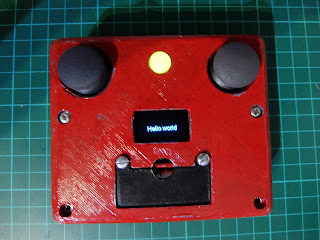
I want my robot to turn itself off when the batteries get low. Battery protector boards generally have a weakness: they are meant to be part of the battery. If you remove the battery from them, you need to charge the battery through them to reset them, so then you need an integrated charger in your robot. This would be convenient: to charge the robot by plugging it into a USB socket. I bought some TP4056 boards - the ones with out+/- as well is battery connectors, but it turns out they are made with clones of the TP4056 that aren't always safe . That link recommends testing them for at least one charge cycle before using them. That's more trouble than I want to go to right now. I also have one other two cell charger, that was quite a lot more expensive, but really the same risks apply. I'd decided when I designed roundbot with lithium batteries that it would be best to charge the batteries in a UK bought external charger. The point of the chassis design is to provide

Fidget Spinner

Image
One of my daughters friends has a fidget spinner. On the weekend, she and I went looking through the options on Thingiverse. She had something specific in mind. Because of space limitations in my shed, I've deciding painting models is the easiest way to have access to lots of colours. The result is: It takes a long time to finish something: Filler then spray on primer, then 2 coats of colour then two coats of lacquer. Not single coat takes long to do on something small, it's just a matter of doing a bit each morning and night. My daughter does seem to like it, and it'll do her good if she's patient enough to master it. I might try and find some more ergonomic bearing caps though. I'm actually yet to see another spinner to compare it too.

Remote Control

Image
I first thought of building this, because I printed a quad-copter frame, and bought a flight controller, motors and propeller to go with it. I thought I would connect a Wemos D1 mini to the flight controller. Then if I wanted to fly it, I'd need a WiFi remote control. I had two thumb joysticks and Spark-fun breakout boards I bought a long time ago, and never used, so I set about designing something. I also had various ESP 8266 modules to choose from. Having designed and printed something around a NodeMCU V2, I realised I'd made a silly mistake: There's only one analog in. You can often work around this by connecting and disconnecting the power from the various inputs, but that's not possible with these breakout boards. I got a cheap ADS1015 breakout board, and squeezed it in the corner of the box. It's all a bit of a squeeze: I should have made the box a bit bigger. I always underestimate how much room wires take up. I also thought I'd made it for 30mm s

Blockly/Scratch for AdaFruit Circuit playground

I bought a circuit playground from Pimoroni. I'd like to give something physical to my daughter to experiment with programming. Then I realised my first mistake: There's a newer version that has support for graphical programming. Anyway, maybe I didn't want something Microsoft: I have android tablets, and I'm much more likely to hack on something built with Blockly . Perhaps something else will do in the meantime? Ardublockly  compiles to Arduino. Circuit Payground Scratch Computing , although it's not easy to run flash on a tablet any more... This thread provides some starting points for defining your own code generator. It seems like the thing to do is define an interpreter for 'native' Blockly that runs in a micro-controller. I can have a wire encoding for that using canonical s-expressions. Having come this far, I'm suddenly wondering if any of this is a good idea. I don't even think writing a loop is a good way to control things, so I

Soldering a usb wifi module to a raspberry pi zero's test points

Image
I'm sure I found instructions on how to solder a USB wifi module onto a Raspberry Pi Zero somewhere. After seeing that, I bought a couple of little USB modules: Described as RT3070 Ralink Network Card Adapter Module. It works plugged into the Pi's USB port without any problem, so that's a start. Here are the instructions . I was under the mistaken impression you get an extra port out of it, but you don't - you are just using the one usb port. I'm going to cut the cable and use the existing wires. I've got another module, and another cable for testing, if that's needed. They are: red: +5V -> PP1 yellow: D- -> PP23 white: D+ -> PP22 green: ground -> PP6 There's a spreadsheet of test points here . I actually got the D+ and D- the wrong way round the first time, because I found a misleading description of the module, but nothing got broken, and it worked at the second attempt. The order is just as you would expect for a USB co

Robot arm

Image
I 3d printed this robot arm I original found on Thingiverse, but the Instructable is recommended. There's a MK2, and also a delta style arm, both of which look like good alternatives, but this will do for now. Here's a video of it moving: I've attached it to an STM32F4 Nucleo board, via a prototype shield: In the video, I'm sending commands from a python script that runs on my desktop, communicating via USB serial. I've written an implementation of canonical s-expressions in c++ that doesn't require memory allocation, as well as a python version to talk to it. It's the main reason I haven't posted for so long, and of course overkill for just controlling some servos, but should prove more generally useful. Here's the code . It uses platformio for the build, and mbed rtos.

Wire representation of floating point numbers

I have a wire representation for integers (just big endian) and it's easy to work out tests for that. The easiest way to encode floats is then to split into mantissa and exponent. I'd figured that out and was looking for a code example. I'd given up, and was searching for 'convert float to ieee 754 c code', when I finally found this answer, based on my original approach: http://stackoverflow.com/a/14955046

Reverse voltage protection

Image
I mislabelled the batteries in my robot chassis, put the batteries in the wrong way, and loud pop! resulted 😞. The capacitor on the motor driver board had explo ded. It's all soldered together, so the easiest thing to do was build another board. I've done that, and added reverse voltage protection using a mosfet: Wish I'd thought of that before. Anyway, I've built another shield to replace the destroyed one.

I published a thing on Thingiverse

http://www.thingiverse.com/thing:2127404 It's a different solution to the inconvenience of connecting the ST-Link to a Nucleo board: I printed a little block to push the individual connectors into, which holds them in the right place. This makes it quick to make a correct connection. I had to design and print a box for the ST-Link that accommodates the connector blocks. I've actually got the beginnings of a [box building library](https://bitbucket.org/davidji/roundbot/src/29e6f1c9a86ac51f5250e6fd096bca2c78679e78/hardware/boxes.py?at=default&fileviewer=file-view-default).