Posts

Wire representation of floating point numbers

I have a wire representation for integers (just big endian) and it's easy to work out tests for that. The easiest way to encode floats is then to split into mantissa and exponent. I'd figured that out and was looking for a code example. I'd given up, and was searching for 'convert float to ieee 754 c code', when I finally found this answer, based on my original approach: http://stackoverflow.com/a/14955046

Reverse voltage protection

Image
I mislabelled the batteries in my robot chassis, put the batteries in the wrong way, and loud pop! resulted 😞. The capacitor on the motor driver board had explo ded. It's all soldered together, so the easiest thing to do was build another board. I've done that, and added reverse voltage protection using a mosfet: Wish I'd thought of that before. Anyway, I've built another shield to replace the destroyed one.

I published a thing on Thingiverse

http://www.thingiverse.com/thing:2127404 It's a different solution to the inconvenience of connecting the ST-Link to a Nucleo board: I printed a little block to push the individual connectors into, which holds them in the right place. This makes it quick to make a correct connection. I had to design and print a box for the ST-Link that accommodates the connector blocks. I've actually got the beginnings of a [box building library](https://bitbucket.org/davidji/roundbot/src/29e6f1c9a86ac51f5250e6fd096bca2c78679e78/hardware/boxes.py?at=default&fileviewer=file-view-default).

Battery holders and ST-Link

Image
I'm printing a new version of my round robot chassis with PETG. I had one initial objective: to add better battery enclosures, because the batteries on the first one just fell out. So I added some integral ones. I looked around Thingiverse and found these , which led back to these . I actually designed my own: since I needed to resize to CR123, and didn't find the SCAD files all that readable: full of magic numbers... I used the clips from the second design, because they were better specified, and not expensive from rs-components. Anyway, I printed that version in PETG. When I came to get it off the plate, the base layer just stayed on the plate: the adhesion between the plate and the base was greater than the adhesion between the shell and the filling! I've refactored the chassis quite a lot to deal with that. The latest iteration is printing now. The other change was to support a Nucleo 64 board like the STM32F303RE one. I've managed to remove the programmer, ...

IP Camera

I found this Raspberry Pi Zero camera enclosure on Thingiverse. I printed it first using Cura to slice it. That didn't work so well: every 5mm or so, the model had weak layers. I decided it was time to try slic3r instead. Slic3r is much better supported by Prusa Research: you can get a config bundle from the Mac distribution , and I've just installed the Ubuntu version:   $ sudo apt-get install slic3r I was expecting a lower level experience to Cura, but basically it's the same interface: a view of the build plate with the objects on it, and some tabs to configure the options. I definitely won't bother with Cura again. The model itself might benefit from a bit of smoothing around the slots before you put it together. Don't use a nyloc nut in the pivot if you printed with PLA at least: it won't be strong enough. I found out the hard way, but of course I could just print another one. I'm now installing MotionEye as per these instructions . MotionE...

Cura for Ubuntu 16.04

I started writing a post about building Cura for Ubuntu from source. It turned into an Epic. I suppose I should have checked that it had sane python packaging before I started. It doesn't. The maintainers have resorted to one of those horrible check it and all it's dependencies and build then all scripts, that are always completely impenetrable when they don't work. Thankfully, someone with much more patience than me has done it already. It's here .

Building a Prusa i3 Mk2

Image
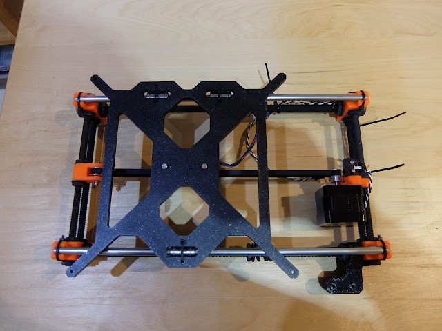
I'm quite a long way though the build. I spent about 2 hours on it on Tuesday night and another 2 hours last night. I have the extruder mounted on the X-Axis, so basically all the mechanical parts are done. I've messed up a few things: I couldn't get the rods fully into the X-Axis motor mount, until I resorted to using a hammer. Also, when I slid the X-Axis on, I wrecked one of the bearings. Fortunately I had a spare lying around. Here are some of the sub-assemblies: the Y-Axis: The troublesome, too long X-Axis: I think I have the hang of the instructions now. It's pretty easy to not get everything oriented correctly: for example, the cable management depends on the correct orientation of the motors and fans. I still managed to put the extruder fan in the wrong way the first time. It's an annoying mistake, because where the screws are tapped into plastic parts they are very stiff! I have to say, I feel the whole thing is a bit flimsy, and I'l...