Posts

Pesky Digispark clones and stepper motors

Image
I'm building this cable car I found on Thingiverse. I actually started on this version , driven by a cheap stepper motor. Neither quite fits my needs: I want to mount it on the underside of a bunk bed. I settled on this idea of a usb stepper motor. I.e. a stepper motor powered and controlled via a USB connection. A Digispark ATTiny85 has 4 wires left over after USB. The stepper motor is a  28BYJ-48 . It's a unipolar stepper motor, and the driver board that came with it is enormous! I'm sure it's only economic because there's some enormous stockpile of ULN2003A chips somewhere that makes them basically free, or maybe a stockpile of actual boards. Anyway, This post explains quite well how to convert it to a bipolar stepper motor . Then I can use a DRV8835 driver carrier board, which will work at 5V and is really cheap (as low as $1.50). I've designed a mount/enclosure that looks like this: Unfortunately all I was getting the stepper motor to do was buz...

RIOT-OS

I've just stumbled on RIOT-OS , because it claims to run on an STM32F030, and I have one of those minimum system boards you can get for £1 on eBay, and I was wondering what open source support there was for it. It has a design principle I'm keen on: it's batteries included. I has a micro kernel, but also provides consistent APIs for a number of platforms. The list is impressive. Anyway - time will tell: MBED tries to do this too, but it's resource requirements are too great for many of the platforms listed by RIOT-OS, which suggests it's a lot leaner than MBED.

Current limiting for battery protection

Having figured out how to add under voltage shutdown, and reverse voltage protection for lithium battery powered modules, I obviously also need to look at over-current protection: I don't want a motor stall to set a battery on fire. Current limiting with discrete components isn't that hard, but it involves lots of components and lots of testing. The result is probably just too big. I wanted to see if there was a reasonably priced integrated solution. Anyway, it's worth observing that accuracy of a simple transistor pair is ±30%, just to set expectations on accuracy. These turn out to be called smart switches, or current limit switches. It's not easy to do parametric search on these: they have different features, as well as basics like current, voltage handling and Rds(on). Some searches: Farnell Some of these have current feedback. I.e. they have a pin which is a current source that's some fraction of the output current. They all have thermal shutdown to ...

VSCode

I've been trying out VSCode for golang at work. It's super fast, and gives the same experience on Mac and Linux, so I'm going to try adopting it for a few different purposes. I'm pretty unhappy with Eclipse CDT for Chibios development: I want to index to be separate for each project. Without that, it doesn't work out any of the conditional compilation, and reports lots of spurious errors. No problem doing that in VSCode, so I decided to try that first. You do seem to be expected to write a JSON config file with the include path by hand, however. Rather than do that, I wrote a little script which parses the build output and generates the file. Once that's done, IntelliSense works perfectly.

Off switch

Image
I want my robot to turn itself off when the batteries get low. Battery protector boards generally have a weakness: they are meant to be part of the battery. If you remove the battery from them, you need to charge the battery through them to reset them, so then you need an integrated charger in your robot. This would be convenient: to charge the robot by plugging it into a USB socket. I bought some TP4056 boards - the ones with out+/- as well is battery connectors, but it turns out they are made with clones of the TP4056 that aren't always safe . That link recommends testing them for at least one charge cycle before using them. That's more trouble than I want to go to right now. I also have one other two cell charger, that was quite a lot more expensive, but really the same risks apply. I'd decided when I designed roundbot with lithium batteries that it would be best to charge the batteries in a UK bought external charger. The point of the chassis design is to provide ...

Fidget Spinner

Image
One of my daughters friends has a fidget spinner. On the weekend, she and I went looking through the options on Thingiverse. She had something specific in mind. Because of space limitations in my shed, I've deciding painting models is the easiest way to have access to lots of colours. The result is: It takes a long time to finish something: Filler then spray on primer, then 2 coats of colour then two coats of lacquer. Not single coat takes long to do on something small, it's just a matter of doing a bit each morning and night. My daughter does seem to like it, and it'll do her good if she's patient enough to master it. I might try and find some more ergonomic bearing caps though. I'm actually yet to see another spinner to compare it too.

Remote Control

Image
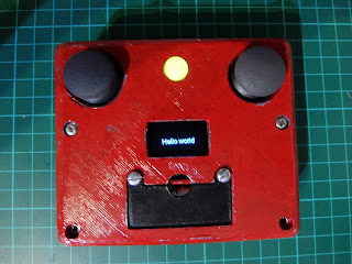
I first thought of building this, because I printed a quad-copter frame, and bought a flight controller, motors and propeller to go with it. I thought I would connect a Wemos D1 mini to the flight controller. Then if I wanted to fly it, I'd need a WiFi remote control. I had two thumb joysticks and Spark-fun breakout boards I bought a long time ago, and never used, so I set about designing something. I also had various ESP 8266 modules to choose from. Having designed and printed something around a NodeMCU V2, I realised I'd made a silly mistake: There's only one analog in. You can often work around this by connecting and disconnecting the power from the various inputs, but that's not possible with these breakout boards. I got a cheap ADS1015 breakout board, and squeezed it in the corner of the box. It's all a bit of a squeeze: I should have made the box a bit bigger. I always underestimate how much room wires take up. I also thought I'd made it for 30mm s...